Volga DWDM System I OTN X-Connect
Russian backbone OTN cross-connect for DWDM networks
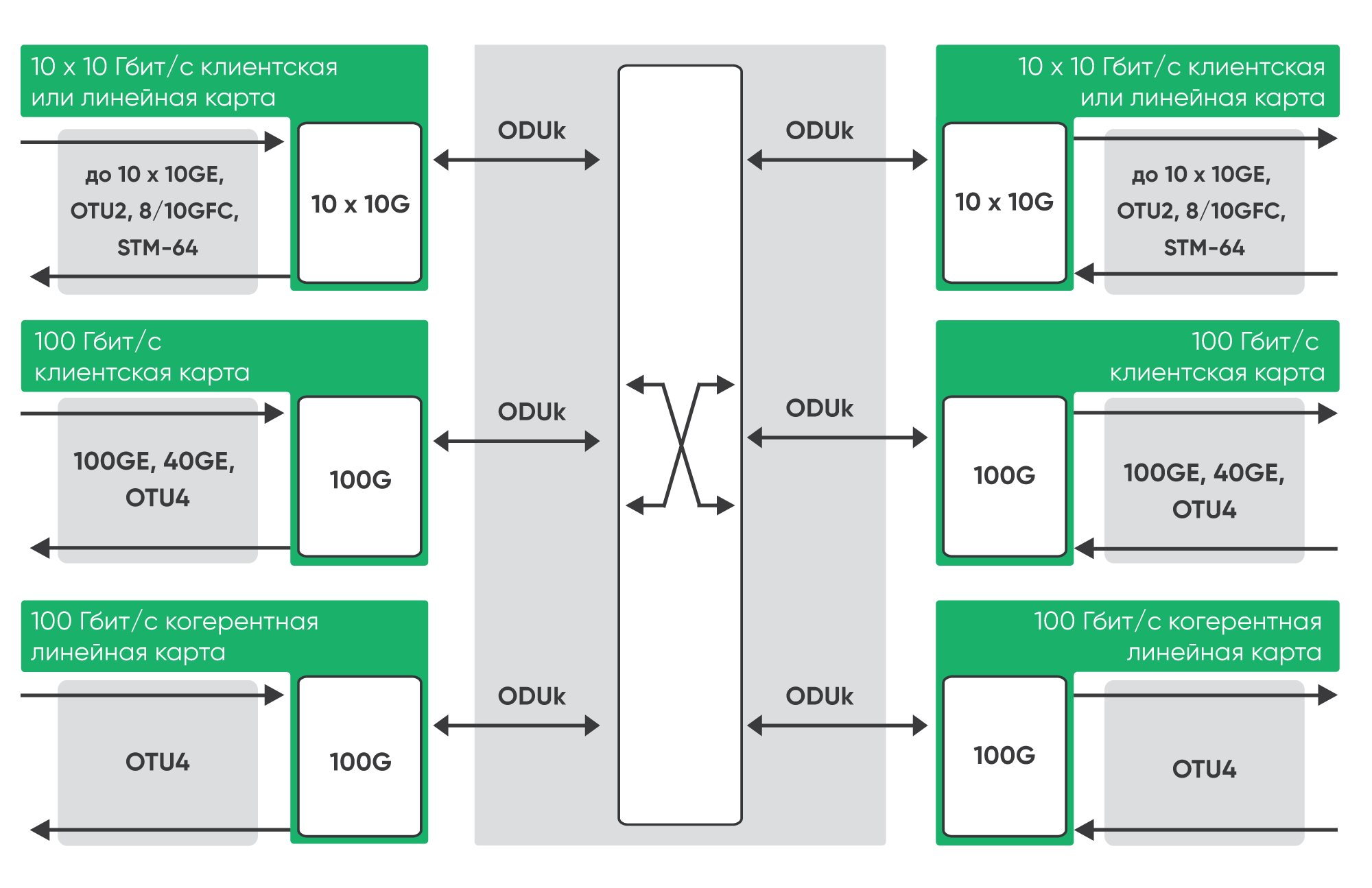
Volga OTN cross-connect switches ODU streams at ODU1/2/3/4 levels in a non-blocking mode. The XC2T model has a bandwidth of up to 2 Tbit/s. A centralized OTN cross-connect fabric (OTN XC) system with a capacity of 4 Tbit/s is under development. The cross-connect matrix provides the possibility to place a variety of client signals in the payload of OTN containers ODU-k (k = 0/1/2/3/4), and then programmatically redistribute them between different OTN optical channels OTU-k (k = 1/2/3/4), i.e. between line ports tuned to different wavelengths.
This allows the operator to manage the distribution of client port traffic across transport channels more efficiently. Each client port is no longer rigidly associated with a specific transport channel (as in a muxponder). Traffic can be switched to any transport interface through the NMS or automatic traffic redistribution can be configured depending on the channel load.
OTN technology is the successor to SDH circuit switching technology, with VC-x cross-connect as a key element. OTN cross-connect ODU-k channels includes the best SDH features such as:
• Add-Drop & Continue: copy the same service channel, for example, in two independent directions (line outputs) and at different wavelengths
• SNCP protection switches at the ODU-k level organization
The hardware architecture of the WDM/OTN cross-switch implies the presence in the chassis of separate line cards (DWDM side) and tributary cards (client interface side), interconnected by an OTN cross-connect matrix. Along with this, for example, in the new XC900 chassis it will be possible to use two slots for conventional transponders.
OTN technology is used in conjunction with DWDM technology, where several OTN ODU-k channels of different levels at different wavelengths can be transmitted simultaneously on one fiber. Today, a combination of OTN and DWDM technologies is the most common solution for building modern fiber-optic telecommunication networks.
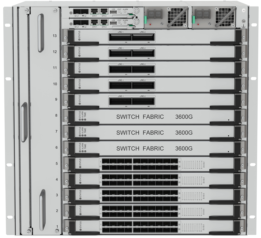
Volga cross-connect
Units for Volga series chassis with OTN-switching
| Parameters / Chassis | XC9R2 | V10R2-X2 | V10R2-X4* |
| Chassis switching capacity | 900 G | 2 T | 4 T |
| Number of cards | 11+2 (out of cross connect for transponders) | 13 | |
| X-connect cards | 2 | 3 | |
| Line cards | 100G | 1x200G, 2х100G, 2x200G | |
| Types of client cards | 10х10G (10GE, STM-64, OTU2, 10GFC, 100GE) | 2x100G, 20x10G (10GE, STM-64, OTU2), 10GFC, 100GE, 40G, STM-256 | |
| Redundancy X-connect cards | 1+1 | 2+1 | |
| Redundant control units | 1+1 | ||
| Sync block reservations | 1+1 | ||
| Power supply redundancy | 1+1 | ||
*in developing
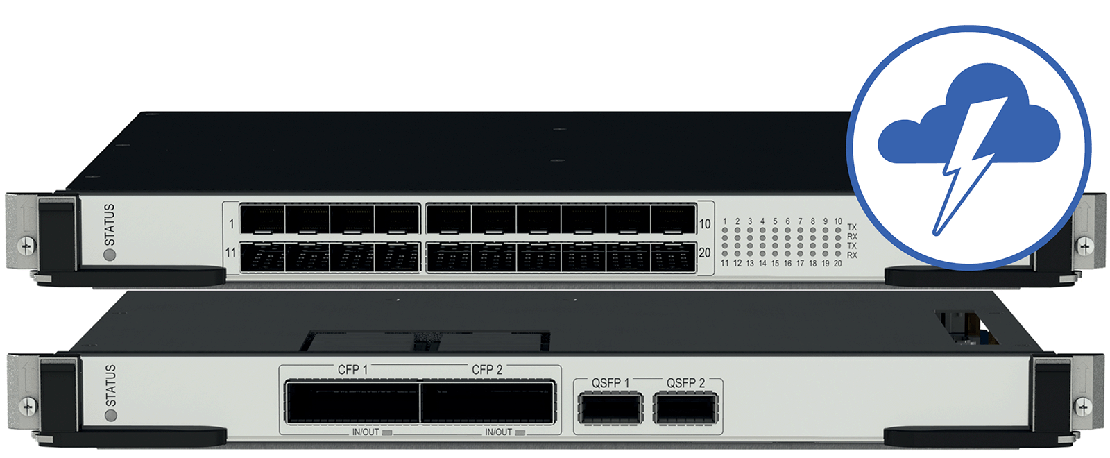
Line Card Features
Line Cards | Operating Mode | |||
L400-2C2-X2 | L200-1C2-X2 | L100-1C-X2 | L200-2C2-X2 | |
| Number of interfaces | 2 | 1 | 1 | 2 |
| Interface type | CFP2 | CFP | CFP2 | |
| Modulation format | DP-8QAM | DP-QPSK | ||
| Frequency grid | 50/100 GHz | |||
| Automatic dispersion correction | up to ± 20 ns/nm | до ± 50 ns/nm | до ± 40 ns/nm | |
| Wavelength range | 1528.7-1567.1 nm | |||
| OSNRτ (0,1 nm, BER=10-¹²) | 18.1 dB | 12.5 dB | 11.4 dB | |
| FEC | SD-FEC 15% | |||
| Output power (BER=10-¹²) | -15…+1 dBm | -5...0 dBm | -15…+1 dBm | |
| Receiver sensitivity | -22 dBm | -18 dBm | -22 dBm | |
| Receiver overload | 0 dBm | |||
| Lightning protection | 1.6 Mrad/s | 1.6 Mrad/s | 50 Krad/s | 5 Mrad/s |
| Power consumption | 150 W | 130 W | 110 W | 130 W |
Client Card Features
| Client Cards | Operating Mode | |||
C100-10P-X1 | C200-20P-X2 | C200-2Q-X2 | C100-2Q1P-X1 | |
| Quantity and interface type | 10 (SFP+) | 20 (SFP+ / SFP28) | 2 x (QSFP+/QSFP28) | 2 x (QSFP+/QSFP28) + 1 x SFP+/SFP28 |
| Interface standard | 10GE/OTU2/STM-64/FC | 10GE, OTU2, | 40GE/OTU3/ | 10GE, OTU2, STM-64, |
| Power consumption | 100 W | 150 W | 110 W | 130 W |