DWDM technology basics
Chapter navigation:
1. Introduction to DWDM technology
2. Main components of the DWDM system
3. Causes of errors in the DWDM system when receiving an optical signal
4. Methods to increase the performance of DWDM systems
5. Flexibility and scalability of modern optical transport systems
Introduction to DWDM technology
Today the term “DWDM” is associated with a wide range of technologies, solutions and standards for the communication and transmission of data. Constantly appearing types of services and new user applications create an ever-increasing load on the main transport network. This means that for highspeed traffic transporting, it is required a data transfer technology, which, on the one hand, has sufficient performance, and on the other hand, provides to operator opportunities to scale the network without changing the infrastructure. These requirements are satisfied by the spectral multiplexing technology (WDM – Wavelength Division Multiplexing), which has been the main technology for building backbone fiber optic communication networks for almost 30 years.
WDM is a physical layer technology that allows you to simultaneously transmit several information channels over a single optical fiber using various light wavelengths. Channels can be added gradually and have different speeds and transmission formats. That allows operators to increase network capacity and develop various types of services on an existing network without laying additional fibers.
DWDM VOLGA
The first WDM systems were two-channel with transmission at 1310 and 1550 nm. Somewhat later, appeared multichannel solutions: CWDM (Coarse Wavelength Division Multiplexing ) and DWDM (Dense Wavelength Division Multiplexing), where the names indicate the density of the information channels in the optical spectrum.
CWDM is a coarse spectral multiplexing technology that provides transmission in a wide range from 1260 to 1625 nm to 18 optical channels with a step of 20 nm between them. The CWDM system does not assume the presence of optical amplifiers in the line, since most of the channels do not fall within the operating wavelength range of the erbium amplifier, which means that the maximum length of the regeneration section is limited by the transceiver parameters and the physical properties of the fiber. However, due to the greater inter-channel distance, the requirements for the construction of transceiver modules (transceivers) and passive optics, in particular, multiplexers, are reduced. As a result, the cost of CWDM solutions is lower compared to DWDM.
Therefore, the use of coarse spectral multiplexing technology is expedient where a low-cost solution with a small distance between subscribers is required, the required bandwidth does not exceed 10 Gbit/s per channel, and the system does not scale up to a significant increase in the number of carriers.
The Erbium Doped Fiber Amplifiers (EDFA) in the early 1990s gave a powerful impact to the development of DWDM systems. An erbium amplifier allows evenly enhancing information channels at different wavelengths just in that spectral range of the optical fiber, where the signal attenuation is minimal (C-band, 1530 - 1565 nm). Thus, the appearance of erbium amplifiers has opened up the possibility of constructing multichannel systems that allow data transmission over long distances without electrical signal regeneration.
DWDM transmission technology creates the basis for the organization of flexible highspeed intelligent networks, ensuring the transparent transmission of ever-growing traffic, including sensitive to delays. The technology supports speeds from 150 Mbit/s to 600 Gbit/s per wavelength. A number of vendors in active development have more then 600 Gigabit solutions.
DWDM can be used not only for the organization of backbone communication systems between large settlements, but also in urban optical networks. Another trend in the development of DWDM systems is set by the largest data processing centers that are pushing developers and equipment manufacturers to develop new technical solutions to increase the capacity of existing transmission systems over optical fibers, which for operators means a reduction per bit/s.
A new direction, where in the near future the technology will be in demand, is aggregation and transparent transfer of traffic that is critical for delays. Therefore, the transport core of the developing 5G networks will undoubtedly be built on the DWDM principle.
Main components of the DWDM system
Transponders/Aggregating transponders
Adaptation of client signals to DWDM networks can be carried out using blocks of transponders and muxponders (aggregating transponders). These blocks are used to convert the carrier wavelength of the signal coming from the client equipment to the established WDM frequency plan, and the optical signal coming from the line are converted to the carrier wavelength of the client equipment, i.e. they combine transmitting and the receiving part.
Let us consider in more detail the functional of transponders and aggregating transponders in a general form, and further explain the difference between them. Both devices transmit a linear signal at the desired wavelength within the selected spectral compaction format. The components in the transmitting part (lasers and modulators), as well as forward error correction (FEC) algorithms, ensure that it is sufficiently resistant to noise and distortion. Using in blocks of transponders/aggregating transponders with modern formats modulation enables high network capacity. On the other hand, transceiver modules provide a transparent transformation of various client interfaces into linear ones with monitoring and error control capabilities.
The functionality of transponders and aggregating transponders is expanded by supporting solutions of the operator class. Measures are being taken to increase reliability, continuous operation time, reduce restart time; remote monitoring is provided. Modern modules can support the Software Defined Network (SDN) architecture. The transponder has a number of output ports equal to the number of client ports. Depending on the implementation, it may have the function of internal switching or rigidly connect input and output ports to each other in pairs.
In the case of using OTN (Optical Transport Network) technology, working in conjunction with DWDM and ensuring the transfer of heterogeneous traffic to the optical level, the device’s task is to encapsulate the client signal into low-order ODU frames (Optical Data Unit), add a header for FEC error correction procedures and the formation of the output digital frame. Such a procedure is called a mapping, and the output digital frame modulating an optical carrier is called an OTU (Optical Transport Unit).

SD-FEC is a thirdgeneration coding algorithm that provides data transmission for optical 100G networks over long distances and with large relay sections.
Unlike a usual transponder, the aggregating transponder not only converts the client signal into the OTN frame format, but also performs the functions of digital multiplexing. As in the transponder, at the first stage, customer data is placed in low-order frames (often referred to as the Tributary ODU in OTN). The OTN multiplexer synchronously multiplexes low-order ODUs into high-order ODUs (Line ODU).
A checksum is calculated from the group frame, and only one OTU linear frame is generated at the output of the multiplexer. Accordingly, the aggregating transponder forms one optical channel. The radiation wavelength is usually tuned in the operating range.
On the receiving side, signals arriving at the transponder input are detected and reconstructed by a digital photodetector. In the case of the implemented FEC error correction procedure, the corresponding blocks detect and eliminate errors that occur during the propagation of the signal over the line of communication.
The main components of the DWDM system:
- transponders/aggregating transponders that generate signals at different wavelengths;
- multiplexers, combining signals from different fibers at different wavelengths in a single fiber, and demultiplexers separating several signals at different wavelengths from a single fiber into different fibers;
- amplifiers that amplify a multichannel signal when it is transmitted through an optical fiber.
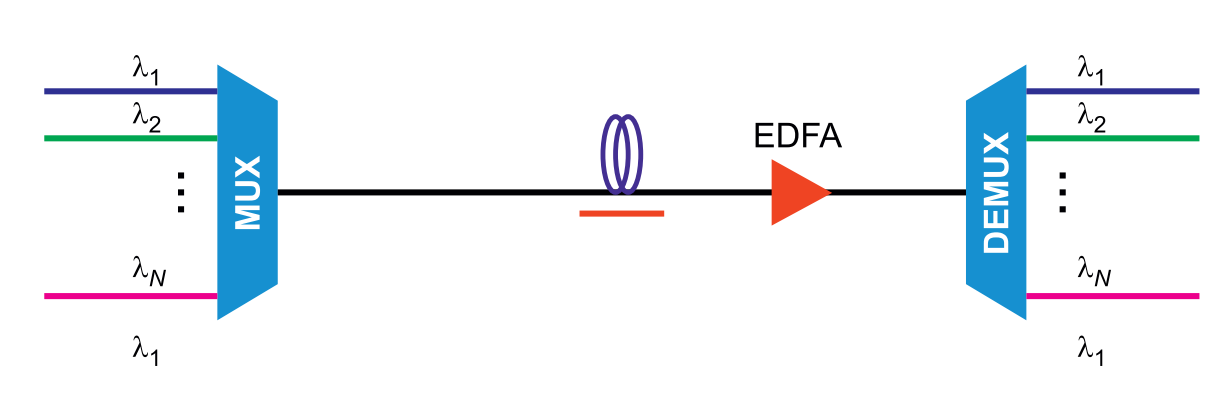
Figure 1. General view of a WDM system with transmission of optical signals through a single fiber at different wavelengths

There are many FEC coding algorithms that differ in complexity and performance. One of the most common FEC first generation codes is the ReedSolomon code (255, 239).
Optical multiplexers
Multiplexers are divided according to the possibility of changing the channel plan and the number of channels. In the first classification, two groups can be distinguished: fixed, when each optical channel is directed to a rigidly pre-set fiber, and tunable ROADM (Reconfigurable Optical Add-Drop Multiplexer) in which you can programmatically change the distribution of channels across
ibers. By the number of channels, there are terminal (multi-channel), where the number of channels N = 40 - 96 and the OADM (Optical Add-Drop Multiplexer) input-output multiplexers with the number of input / output channels from 1 to 16.
All transponders (aggregating transponders) are connected to an optical terminal multiplexer - a passive device that allows you to combine previously formed optical channels into a single optical fiber. On the receiving side, the demultiplexing of the optical signal occurs — the inverse operation to the multiplexing procedure.
It is the multiplexers / demultiplexers that are pure WDM devices, since their parameters determine the frequency plan of the communication system: the density of the channels, their number, the bandwidth of each channel.
Fixed multichannel multiplexers are made on the basis of AWG arrays (Array Waveguide Grating), and low-channel multiplexers can be implemented as a set of TFF filters (Thin Film Filter). The loss per channel in multiplexers based on AWG-grids does not depend on the number of channels and is approximately 5 dB.
For low-channel multiplexers, the losses are determined by the number of successively included filters (usually the number of channels N = 2 ^ m, where m = 1–4, the number of consecutively connected filters) and range from 1.5 to 6 dB. The limitation on the number of channels (8–16) of smallchannel multiplexers is caused by the fact that the losses in the filter cascade are compared with the losses in the AWG-grid of the multi-channel multiplexer.
To form a uniform group signal, devices can contain controlled optical attenuators for each multiplexing channel. In addition, they can be equipped with channel power meters for remote monitoring of the spectrum of channels, as well as a monitor connector for connecting measuring equipment without breaking the optical line.
Reconfigurable optical add-drop multiplexer ROADM
The group of software-reconfigurable optical add-drop multiplexers should be considered separately.
While fixed multiplexers (OADMs) rigidly determine the channel routes, then the flexibility and scalability of the system can be achieved using a reconfigurable multiplexer — ROADM (Reconfigurable Optical Add / Drop Multiplexer), which programmatically changes the channel distribution over the fibers (Figure 2).
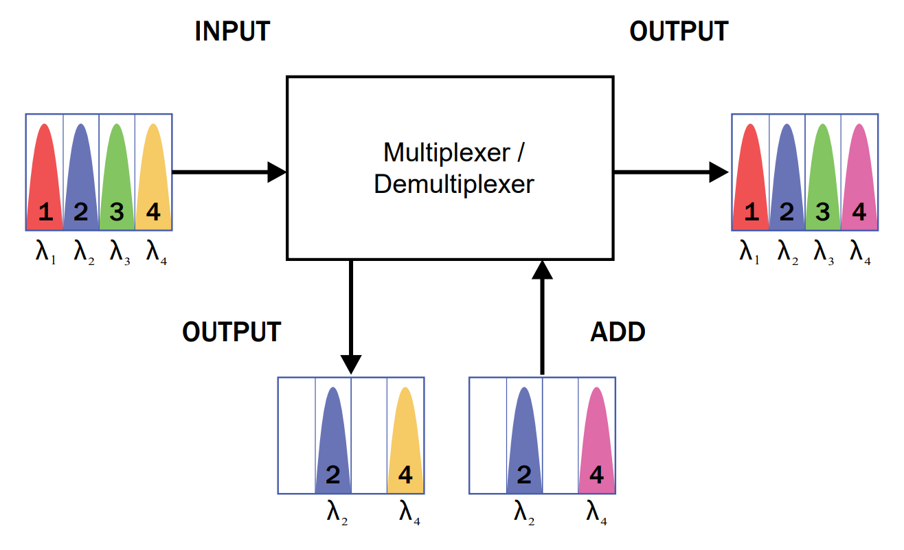
Figure 2. Principle of operation of a reconfigurable multiplexer input-output (ROADM)

Due to the technology of selective switching of spectral channels (WSS), ROADM provides flexible control of spectral channels and allows building mixed networks of any topology. The ROADM node can switch the spectral channel to the input / output and pass-through transmission without interrupting the traffic.
The number of WSS matrices (Wavelength Selective Switch), the main components of ROADM, determines the functionality of the I / O multiplexer and the number of available directions. The WSS matrix directs the wavelength arriving at the input port to any of the N outputs. With the advent of precision technologies at the photon level, it became possible to use the spectral resource more efficiently due to the high granularity of WSS devices.
Line signal transmission. Optical fiber. Optical amplifier
The transmission of the formed group optical signal is performing on special optical telecommunication fibers. For the most of systems, which use DWDM technology, standard single-mode fibers (SSMF) are considered optimal, the parameters of which are determined by the recommendation of ITU G.652.
A fiber with a core of pure quartz (PSCF - Pure Silica Core Fiber, recommendation G.654D) has been developed special for using in long DWDM-systems. Typical use of such fibers - underwater communication lines.
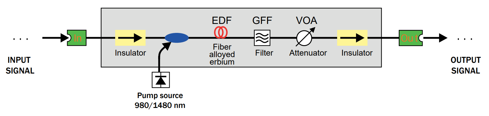
Figure 3. The simplest scheme of single-cascade EDFA amplifier.
Fibers with a super-large-effective-area (SLA) can be used for systems with a large number of channels. In these fibers, nonlinear distortions reduces and the permissible signal power increases, which ultimately leads to an increase of the non-regenerative signal transmission length in the fiber-optic communication line. A fiber with reduced sensitivity to bending loss can be used to facilitate the installation and insertion. It is described by the recommendation G.657.
Optical fiber is a source of attenuation, which means that special devices need to be placed on the line – optical amplifiers that restore the level of optical radiation, thereby increasing the transmission distance. The typical distance between the amplification nodes is from 60 to 100 km; it is optimized for each projected line.
Amplifiers, which can be based on various physical processes are used for optical communication systems. The most popular amplifiers are based on a fiber, which doped with Erbium ions - EDFA (Erbium Doped Fiber Amplifier). Such devices effectively amplify signals in the C-range of the spectral region of the lowest absorption of quartz glass 1535 ... 1565 nm.
The structure of the simplest single-cascade amplifier is shown in Fig. 3. Optical pumping can forward or backward, with one or several lasers emitting at wavelengths of 980 or 1480 nm. Erbium ions absorb the pump energy, change to the excited state. By interacting with signal radiation at a wavelength of 1550 nm, the excited Erbium ion changes to the ground state, accompanied by emission of a single photon at a wavelength of 1550 nm.
In modern multichannel long DWDM systems, the use of single-cascade amplifiers is inefficient. As a rule, multi-cascade schemes are used to adjust the required ratio by controlling the built-in attenuator in VGA devices (Variable Gain Amplifier). The spectrum of the group signal can be aligned by use of GFF (Gain Flattening Filter).
Except EDFA-amplifiers, fiber amplifiers using Raman scattering can be used in communication technology. Amplifiers, which based on the Raman effect can be point or distributed. If point amplifiers are similar in their operational properties to EDFA devices, the use of distributed amplifiers requires enhanced safety measures due to the high power of the pump laser and the good parameters of the fiber optic line. Raman amplifiers are indispensable for large spans (over 150 km), where there is no possibility of organizing a large number of intermediate reinforcement points.
In the early classification of optical amplifiers, the following groups were distinguished by functional purpose: power amplifiers or boosters that are installed immediately after the optical multiplexer; linear amplifiers at intermediate points of extended communication lines; preamplifiers at the input of the demultiplexer to achieve the optimal signal level at the input of the optical receivers. However, manufacturers of DWDM systems are moving away from such a separation, and the amplifier parameters are selected directly under the projected line, taking into account the non-ideal amplitude frequency characteristic of all active and passive components of the system.
Raman scattering (Raman effect) is the inelastic scattering of optical radiation on substance molecules (solid, liquid or gaseous), accompanied by a noticeable change in the emission frequency.
Causes of errors in the DWDM system when receiving an optical signall
Before considering the methods of the DWDM-system performance increasing and optical transport networks modernization as a whole, let us consider several causes of errors in the reception. Receiver noise (or pulses, reduces the extinction and hinders their acceptance. Noises of ASE (Amplified Spontaneous Emission) accumulate when the group signal passes through the optical amplifiers.
As a rule, in lines without amplification the main causes of errors are dispersion, noise and overload at the receiver. The introduction of optical amplifiers changes the problem nature from fundamental to engineering: before sending a signal to the receiver
it is amplified to the optimal level (away from the boundaries of sensitivity and reloading). To compensate the dispersion the line is equipped with special devices – compensators, restoring the pulse duration before the signal injection to the input of the transponder receiving part.
The fee for overcoming the first two causes of errors is ASE noise and nonlinear distortion appearance. The latter is a result of the different line condition in the presence of amplification. Now within the regeneration section there are several (sometimes - several tens) amplifier sections, and at the beginning of each of them, where the intensity of the optical signal is large enough, the signal is suffered from nonlinear effects.
Due to economic reasons, the desire to use the amplifier spectrum more efficiently and to minimize the number of amplifiers in the line leads to the appearance of the spectrum of densely located high-power channels. It leads to the development of intra-channel and inter-channel nonlinear effects.
Transponders and aggregating transponders designed to operate in networks that do not contain optic amplifiers (typically CWDM) are optimized in sensitivity and resistance to dispersion. This is irrelevant for DWDM solutions – it requires channel-forming equipment that is consistent with ASE noise and nonlinear signal distortions.
The permissible boundary parameters of the input optical signal - are the values giving the required error coefficient when other parameters are optimal.
For CWDM equipment the receiver sensitivity and dispersion margins are determined by the same way: the sensitivity – is the minimum permissible power value on the receiver end, at which the undistorted optical signal is received with the specified error value. For DWDM equipment, the main characteristic is resistance to ASE noise. The ASE noise value determines the OSNR parameter (Optical Signal-to-Noise Ratio) and each DWDM transponder/aggregating transponder is described by the required value. The required OSNR is the minimum acceptable OSNR value, such that signal reception is possible within the required BER.
In order to maintain acceptable quality during transmitting the signal, ((SNRT– signal-to-noise ratio) was not lower than the specified value), it is necessary that the fiber bandwidth at the transmission wavelength rises the modulation frequency
Methods to increase the performance of DWDM systems
We define the concept of ‘communication system performance’ as the product of the communication system capacity C full and the transmission distance L. Under a backhaul system distance range is meant the total multihop line transmission distance with 14 intervening amplifiers without signal regeneration. Obviously, the DWDM system performance can be extended in two ways: increasing the communication system capacity and achieving the transmission distance enhancement.
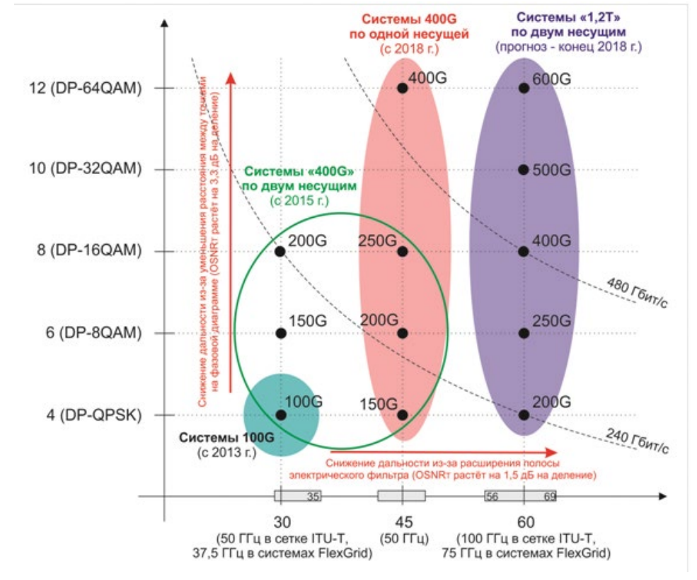
Figure 4. Ways to increase data transfer rate. Horizontally: symbol rate (of Gygasymbol/s) and occupied the optical carrier spectral range. Vertically: the symbolic efficiency (bits/symbol) and the modulation format
Increasing the data transfer rate in the system
The total system capacity with similar channels is determined by the product of the channels number and channel capacity. The last one is determined by two factors: symbol rate and symbol efficiency, figure 4.
The communication system data rate (total bit rate V, bit/s = baud) consists of the data rates in each channel (for a system with the same channels, this is the product of the NCH channels number and the speed VB [bit/s] in each channel). The maximum number of channels in a single fiber pair is set by the current standard of division multiplexing (for example, CWDM, DWDM 100GHz C, DWDM 50GHz C+L). The channel bit rate VB is the product of the symbol rate VS (symbols per second) and symbol rate efficiency of the used modulation format ES (bit/character). In other words, the ES parameter determines the amount of information (bits of data), transfered by single symbol. It’s expressed as the logarithm base 2 of algorithm power (number of values the symbol can take).
System spectral efficiency is the ratio of the data transmission rate (bit/s) to the bandwidth (Hz). It is measured in bit/s/Hz. Spectral efficiency characterizes the efficiency of bandwidth usage in communication system.
1) Symbol rate increase
Symbol rate VS increase is provided by the frequency growth of the transmitter modulator. The limit values of the electric signal symbol rate are determined by the material properties, high-frequency electronics, modulators. From the implementation point of view the available value is about 32 GB on the standart element base. It’s firstly achieved in 100G systems. The 45 Gbaud rate is used in most modern 2×200G processors. The 64 Gbaud values are at the stage of laboratory tests. As the component base is constantly improved, a further slight increase of this parameter is possible, but significant jumps in this direction should not be expected.
2) Multilevel modulation formats
Historically the first amplitude formats of the optical radiation modulation appeared in NRZ (Non-Return-to-Zero) and RZ (Return-to-Zero) modifications, where the RZ code is more resistant to nonlinear effects in the fiber. They provided data rates up to 10 Gbit/s. Use of amplitude modulation was difficult at rates higher than 40 Gbit/s, since the width of the optical spectrum became comparable to the DWDM-system channel space. As well as the of amplitude-modulated signals instability to nonlinear distortions it leads to the phase modulation formats application, where the information codes the optical signal phase or neighboring symbols phase difference (due to the uncertainty of the incoming symbol phase, differential coding is often required).

In the case of amplitude modulation, the power of the transmitter optical radiation is the variable parameter.
Modern solutions use all signal degrees of freedom at the same time: amplitude, phase and light radiation polarization. Today the most common modulation format for 100-Gigabit systems is DP-QPSK (Dual Binary Quadrature Shift Keying), where information is encoded by two polarization states and four phase values (figure 5).
Figure 6 schematically shows the signal generation process in the DP-QPSK format. The continuous radiation of the carrier laser is divided into two orthogonal polarizations, each of them is fed on quadrature modulators and is modulated by an information signal with a bit rate greater than 25 Gbit/s by adding FEC-headers. At the same time, one of the arms of the Mach–Zehnder interferometers, devices based on quadrature modulators, creates a phase shift of 90 degrees by means of the control voltage.
Therefore, QPSK signals are formed in each of the polarizations, which are combined using a polarizing splitter, forming the structure of DP-QPSK. Each character of the format DP-QPSK carries 4 information bits (2 bits/ symbol in each of the polarizations). The transition to the 200G and 400G would also involve the light amplitude. The corresponding modulation formats, DP-16QAM and DP-64QAM, significantly increase spectral efficiency, providing a higher data transfer rate in the usual 50 GHz band.
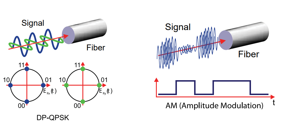
Figure 5. The structure of the signal DP-QPSK and AM
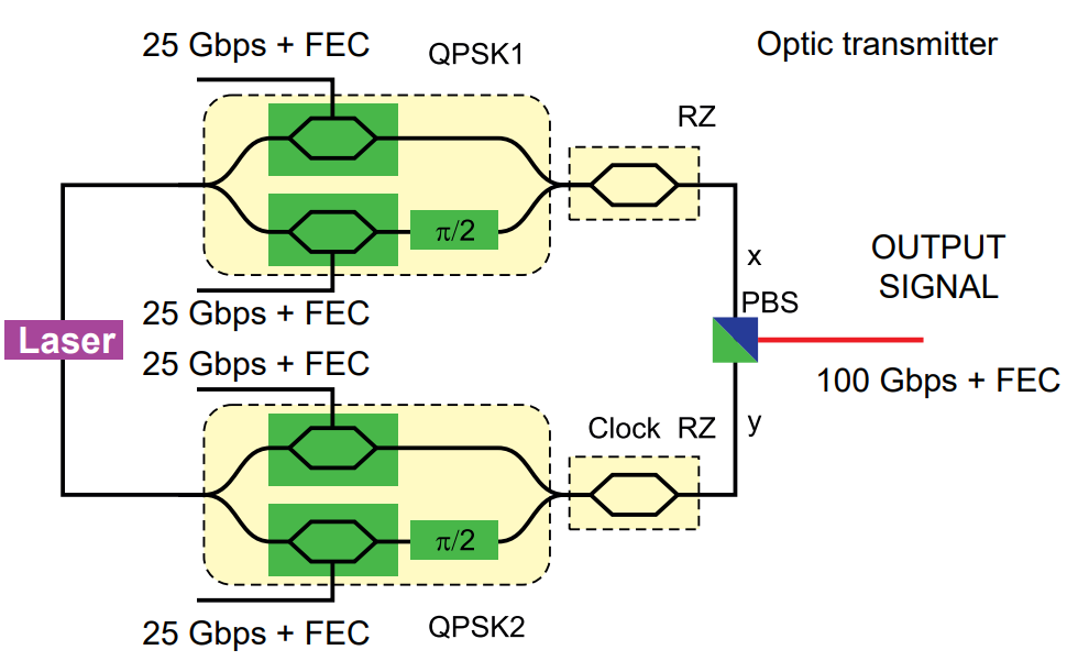
Figure 6. DP-QPSK transmitter structure
From a theoretical perspective, fiberoptical systems can be viewed as classical bandpass systems, to which the modulation theory developed for classical radio communication is applicable.
In modern DWDM-solutions with tight location of optical channels there are no free inter-channel intervals, so the only way of spectral efficiency enhancement is to increase the overall data transfer rate in the system without expanding the used spectral range. This is one of the main reasons for the transition from amplitude to more complex phase coherent modulation format. The fee for such a win is a reduction in the transmission distance.
3) Increasing the number of carriers
The increase of channels number can lead to the new spectral ranges development, restricted by the limited effective band of optical amplifiers.
Another direction is the channel space reduction in the conventional optical range. It requires a transition to a new standard of wavelength division multiplexing and can lead to an interchannel interference augmentation.
The increase in transmission range
The second direction of DWDM-system perfomance enhancement is increasing the distance. It depends on many factors: the sustainability of the selected transponder to the ASE noise and the nonlinear distortion, parameters of the amplifiers and fibers, the channel grid, etc. The receiver sensitivity threshold (dB) also determines the transmission distance. The metric is OSNRr (the required Optical Signal to Noise Ratio) - it is the ratio between signal and the noise levels, when it is still possible to detect the incoming signal.
Operators are often faced with the task of increasing the transmission speed while maintaining the range. Such upgrade may occur by replacing the transponders with better ones preserving the required OSNR.
The benefits of coherent networks consist of the combination of advanced features: amplitude and phase modulation, polarized multiplexing, coherent detection and complex processes of digital signal processing.
1) Coherent reception
To save range, the combination of spectralefficient modulation formats and coherent reception is applied. The coherent detection challenge is to mix the incoming information signal with the radiation of the reference laser. The spectrum transformation is performed so that photodetector contains complete information about the initial optical signal.
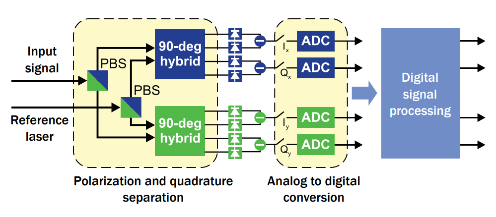
Figure 7. Coherent receiver structure
The structure of the coherent receiver is illustrated in figure 7. Using polarizing splitters, the information signal and the reference receiver laser radiation are divided into two orthogonal components. A 90-degree optical mixer is required for mixing the polarization components of the signal with the X - and Y - components of the receiving laser.
The frequency of the reference laser can be freely switched in the range of ±20 MHz relative to the carrier frequency of the transmitting laser. The laser radiation width does not exceed 100 GHz in modern coherent solutions. Four pairs of signals from balanced photodetectors, improving the receive sensitivity are connected with the inputs of the analog-to-digital converters. Thus, four symbol streams are formed.
Despite the principles of coherent reception have been known for a long time, their optical area application has been hampered. It was caused by the complexity and expensiveness of high stability narrow-band lasers with the need to synchronize the phase and frequency of the received signal and the heterodyne emission. The emergence of powerful digital signal processing technologies solved the problem of phase synchronization. Thus, in the DSP (Digital Signal Processing) block one of the algorithms is a correlation of the phase difference with the use of carrier recovery. It eliminates the need for hardware synchronization of frequencies and hases
of sources.
2) Digital signal processing. Error-free coding.
Today, DSP is an inherent part of a coherent transponder. According to figure 7, four digital streams from the ADC outputs enter the DSP unit, where, with mentioned synchronization and phase diversification, other compensation algorithms necessary for error-free signal recovery are implemented. The first functional processor unit excludes inaccuracies of the input interface – temporal mismatch between the four components due to the inequality of the optical and electrical coherent receiver paths, the inequality of their amplitudes. Then the asynchronous sampling frequency is transformed into the frequency of 2 counts per symbol. The DSP provides compensation for the accumulated chromatic dispersion, which eliminates the need of the installation of a physical compensator making additional losses in the line.
To obtain a distinct phase diagram, it is also necessary to minimize the amplitude deviation from some preset average value.
The rotation of the diagrams in the phase plane is eliminated. The accumulated phase noise, including its nonlinear component, is estimated and compensated. After all processing steps are completed, the values of accepted characters are determined. The last step is the FEC error correction procedure. The use of redundant coding in the multi-level signal digital processing can yield a gain on the required OSNR up to 9 dB. A FEC header is added to the payload in each transponder, with a size determined by the code type.
Flexibility and scalability of modern optical transport systems
The task of achieving flexibility and scalability of optical transport can be divided into several directions: modernization of the system physical components and organization of network manageability at the software level.
Tunable modulation formats. Superchannels The emergence of coherent solutions for DWDM systems was the first step towards improving performance. 100G+ channels provided a significant increase in spectral efficiency. However, the development of coherent technologies did not stop there and opened new development directions. Modern very-large-scale integrated circuits (VLSI), used in transponder blocks, allow to programmatically rearrange the modulation format for coherent channels, scaling the data transfer rate. This functionality allows you to optimize the network, choosing between the distance and the speed for each optical channel.
A superchannel is a set of several optical subcarriers that can be controlled in an optical path as a single unit. The use of several sub-carriers alone does not allow to increase the spectral system efficiency.
As you already know, the transition to a higher modulation level inevitably decreases the transmission distance. But high-speed digital streams (200G+) will be transmitted over long distances using several subcarriers - the superchannel structure. This fact requires the transition from a fixed 50Hz grid to a flexible one solution with granularity up to 12.5 GHz and even 6.25 GHz. These values are the sub-carriers space. The formed superchannel is a single managed structure from the information point of view. Coherent optical channels and super-channels with programmable architecture require a change in the reconfigurable optical ROADM multiplexers architecture to the FlexGrid-CDC configuration detailed below.
ROADM-switching may be applied at the same time with OTN switching.
Commutation at the photon level. CDC FlexGrid ROADMs
After the filling of coherent DWDM channels, including super-channels by traffic, flexible ROADM shall, if necessary, to reallocate the individual wavelengths on the required areas.
The classic configuration of the optical I / o multiplexer was described above. However, the use of super-channels as a way of capacity increasing requires flexibility and scalability from linear devices. An ever expansion of the functionality of the FlexGrid ROADM is inherent in the acronym CDC (Colorless, Directionless, Contentionless).
Function ‘Сolorless’ provides the lack of binding of the wavelength to the ROADM port, so any channel can be add/drop on any port.
‘Directionless’ supports optical routing from the transponder to any of the ROADM directions without binding to the input and output ports. So any channel can be sent to any direction.
'Contentionless' allows the presence of signals at the input ports at the same wavelengths coming from different aggregating transponders. So the same channel can be reused in different directions without causing internal contention in the ROADM.
The physical implementation of CDC FlexROADM has a high cost because it requires a large number of WSS (Wavelength Selective Switch) optical switching matrices. The economic feasibility of using such nodes should be determined for each case specifically.
Where a cheaper solution is required and total program management is not implied, truncated variants (with ROADM, CD ROADM) can be used. Where there is no change in baud rate and the linear signals are not super-channels, high granularity and a Flex solution are not required. Unit ROADM shall support commands carrying by OSC-channel from the control system. This requirement will allow the device to be a software-controlled network node.
In OTN networks, all data received on the input port of the OTN channel are guaranteed to be transmitted to the output port – no TTL, and frames reset. In the case of errors occurring during the transmission in a network OTN, the recovery package through the use of redundant coding takes place.
Commutation at the electrical level
The above was considered a commutation at the wavelengths level where the signal analysis on digital container level does not occur. A more complex variant is the implementation of OTN crossconnect (OXC). The presence of a crossswitching matrix, or so-called switch factory, is a standard requirement from DWDM equipment customers for network topology more complex than ‘point-to-point’. OXC is a controlled integrated circuit that establishes logical connections between the ports of connected client and line cards. In the OTN terminology for every low order ODU a time interval is programly assigned for multiplexing in a certain ODU of a high order.
Building logical connections inside the chassis allows you to create channels of any complexity on the operator's network in automatic mode. The function of flexible reservation of client channels and backhaul links by hot standby mode is provided. Operator doesn’t need to perform manual switching in case of faults.
The specific implementation of the switch factory is determined by the connected line
factory is determined by the connected line cards, which will form the requirements for the cross-matrix bandwidth, its granularity, the internal protocol.
Actually the most interesting thing for converged networks that combine different types of traffic is cross-connect matrices. It perform packets and channel communication simultaneously.
Line cards with both OTN interfaces and Ethernet ports can be connected to such a motherboard, and commutation will take place at the level of proprietary packets inside the device.
SDN. Software-driven networks
The second direction of the transport optical networks development is the introduction of manageability at the software level. Plane) is separated (abstracted) from the underlying user data plane DP (Data Plane).
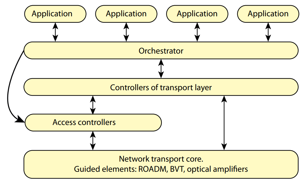
Figure 8. SDN model of transport network
In addition to CP and DP there is an add-in in the form of the so-called orchestrator. The orchestrator manages SDN controllers that monitor the status of various network resources. Controllers collect statistics about all network devices performance and interact with the orchestrator. This high-level device operates with simplified models of lower physical devices and performs the resources end-to-end optimization. Application programming interfaces (APIs) are provided for top-level applications.
Another actual challenge is the integration of SDN technologies with optical equipment and OTN devices. The first one will provide manageability and controllability at the physical level, construction of traffic routes with optimal physical parameters, such as amplification, modulation format, depending on the distance. International alliances such MSA (Multi Source Agreement), develop open specifications for the interaction of the control system with optical devices.
The second direction is the interaction of the control plane with OTN devices. It provides the flexibility in routing at the OTN level. In this case, the devices under control are the OTN transponders and cross-connect units.